
By
Heidi Adkisson
Design systems are essential, but what I hope to show in this article is that a design system alone — particularly if it’s primarily a component level design system — does not guarantee a simple, consistent experience. I believe this because I see it regularly with the enterprise clients I work with. Most (though not all) have moved to a design system. And yet when I look at the result, there are still significant inconsistencies across screens that should be fundamentally similar.
Design systems also don’t prevent what I call “feature tack-on,” where new functionality is merely tacked on to what is already there. Over time, this can create a labyrinth-like application structure. Feature tack-on is particularly endemic with enterprise systems, where customer requests can drive the development of highly specialized features.
How an object model can help
Why haven’t design systems proven to be a silver bullet? One problem is that design systems are often focused at the component level (or use the component level as a starting point). The systems then fail to mature beyond a collection of components.
This is where an object model can help.
An object model is a visual representation of a system’s objects, actions, and associated attributes. An object model can be used, in conjunction with a design system, to create a consistent experience across a system’s higher-level constructs.
What exactly is a higher-level system construct? This idea is illustrated by Brad Frost’s Atomic Design Methodology, which uses a biology metaphor to describe how a design system can be organized. The smallest possible system components (such as an individual button) are considered atoms; atoms, in turn, can be arranged into molecules (for example, a group of components used for global search). Organisms, as a higher-level construct, are a grouping of molecules. The metaphor isn’t perfect, but it does convey the general scheme.

I believe that design systems often struggle to represent higher-level system constructs because there isn’t enough of a framework to identify what should be included there. This issue is what object modeling can address.
Roots of object modeling
The whole idea of interface objects stems from the development of the graphical user interface (GUI). With a GUI, users could directly interact with objects represented on-screen; it was a radical departure from the command-line interfaces in use at the time. The Xerox Star system, released in 1981, was the first commercially-available system with a GUI — and served as inspiration for the Apple Lisa (in 1983) and later the Apple Macintosh (in 1984).


In the 1990s as software began to proliferate, development processes became more formalized, and there was interest in representing software requirements in a consistent manner. UML (Unified Modeling Language) was developed to meet this need. The UML diagrams that are most likely to be familiar to UX-ers even today are the Use Case Model and the Class Diagram.
The Use Case Model is a behavioral model and depicts the system from a task perspective (similar to user stories in Agile).

The Class Diagram is a structural model, which shows a system’s objects and the relationship between them. Each object rectangle includes the object’s associated actions (in the lower pane) and attributes (in the middle pane).

Within development processes reliant on UML, there was an emphasis on object-oriented user interface design, using the Class Diagram as the basis. And, indeed, in the 1990s whole books were written on this methodology.

Admittedly, a complete Class Diagram can be time-consuming to complete and requires a set of analysis skills more typical of an engineer or analyst. It’s not something a UX professional today would typically prepare.
I would argue, however, that object-orientation is a lost and necessary part of UX design, particularly for more complex applications.
The narrative object model
What I am proposing is a simplified object model I call a Narrative Object Model — narrative because it substantially replaces the UML notation with plain-English narrative. Also, while the Class Diagram is highly structured, following the rules of UML, the Narrative Object Model is lighter-weight and more flexible.
Creating a narrative object model
In this next section, we’ll walk through the process of creating a model, breaking the process into three steps:
- Identifying the Objects
- Characterizing the Relationship Between Objects
- Identifying each Object’s Actions and Attributes
Source materials for the model
Creating the model starts with identifying the source materials you have available. What sorts of artifacts do you have that describe or otherwise depict intended functionality?
In my consulting work, I usually am starting with an existing system that we will redesign or re-envision in some way. Starting the model by inspecting that system’s existing interface accomplishes two things: 1) it gets me intimately familiar with that system in its current state 2) it provides a baseline object model that can then be extended to depict the desired future-state.
The other primary source for an object model is user stories or other requirements-oriented artifacts. For greenfield design work, these may be the only sources available.
We’ll begin an example model by looking at an existing interface, using the relatively simple example of Twitter.com.
First, however, it’s important to define two central concepts: an object and an action. Simply stated, objects are the nouns in a system and actions are the verbs. In an existing interface, menus and button bars often contain clues to a system’s objects and actions.
When working with objects, it’s also important to remember the difference between the object, which represents the concept, and an instance of an object. For example, most systems have the concept of an Account, which would be an object. However, there are many instances of an Account: the account of Louise Hughes, the account of Ramon Woods, etc.
Identifying objects
Below is a screen capture of a Tweet from Twitter.com. We have a button bar below the Tweet and a menu (shown expanded) to the right. We’ll use these to identify some nouns (aka objects).
 and menu (right) can be a source for identifying objects.")
Looking at the menu labels, I can see that one noun is a Tweet. We have for example:
- Copy Link to Tweet
- Embed Tweet
- Report Tweet
- I don’t like this Tweet
Additional nouns I can identify are:
- An Account, represented in this case by the account name Fine Cooking Mag (an instance of the Account).
- A Moment, indicated by the menu item “Add to new Moment.”
- A Direct Message, indicated by the envelope icon which means “Send Direct Message.”
The marked-up screen capture below shows the objects we’ve identified thus far:

In our model, the objects become titled rectangles that we will connect together to show relationships. Here are our object rectangles so far:

We definitely can (and will) do more with our objects. However, sometimes if I’m trying to make sense of a poorly organized system, it’s enough, at least initially, to get the objects identified and laid out on a page.
I find the most logical next step, once I’ve identified the objects, is to identify the relationships between objects.
Relationship between objects
Revisiting the UML Class Diagram, you’ll note there is a somewhat cryptic notation scheme for depicting relationships between objects. This scheme involves notating multiplicity of the relationship and showing relationship types using different line-end treatments.

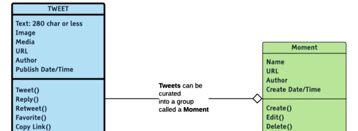
Rather than rely on notation to characterize the relationship between objects, the Narrative Object Model uses descriptive text. The diagram below shows the objects we’ve identified thus far with their relationships described.

The descriptions help illuminate the purpose of each object in context of the larger whole:
- An Account can send a Direct Message
- An Account can publish Tweets
- Tweets can be curated into groups call Moments
Again you could stop your model at this point, after the relationships have been defined, if you feel the model serves your purpose. However, it can be helpful to fill in more information about each object…specifically its associated actions and attributes.
Identifying actions
Next, let’s identify some Actions associated with a Tweet. We can again use the button bar and menu as a starting point:
 identified using a Tweet’s button bar an menu.")
In an object, the actions are listed in the bottom pane of the object rectangle, as shown below.

A stylistic note: I retain the traditional notation for actions in an object model, appending each action with parens. This notation is a preference on my part (completely unnecessary), but it does help visually distinguish actions, which can be helpful on larger, more complex object models.
Note also that I’ve added some actions that aren’t depicted in the screen capture of the Tweet, but are found elsewhere in the interface — for example, the ability to remove a Tweet from a Moment.
We’ll now fast-forward and assume that I’ve repeated identifying actions for our remaining objects. Here is what the model looks like at this point:

Identifying attributes
It’s easiest to think of attributes as the data fields associated with each object. Attributes are what characterize each instance of an object; they listed are in the middle pane of the object rectangle, as shown below for the Tweet object:
 and actions (lower pane).")
Here again, I’ve retained some notation from a Class Diagram. The colon after the attribute Text indicates the type of data — in this case, the fact that Text is limited in length (280 characters or less). I’ve only included data type for the Text attribute because I’ve deemed it to be especially meaningful to the user experience.
Building out the model
Next, let’s look at our model more fully built-out, with some additional elements added to it.

In addition to including more objects, I’ve added some visual elements to help me interpret the model more easily. These include:
- Indicating which objects are the core system objects (in bold outline)
- Using traditional UML line-end treatments to characterize relationships further
- Using color to associate objects with a similar purpose
Indicating core system objects
Not every object is of equal importance in a system. Some objects represent a system’s unique value proposition or are otherwise central to the experience. It usually makes sense to design conventions for the core objects first and then extend the conventions out to other objects in the system.
For Twitter, I’ve indicated the Tweet and the Timeline objects as core, capitalizing the object name and using a bold outline treatment.
Indicating specific types of object relationships
In the model, it can be helpful to represent specific types of relationships. Relationship types illuminate more about the objects and how they might be treated from a design perspective.
The four main types of relationships are:
- Association
- Aggregation
- Component
- Inheritance
Association relationship
The simplest type of relationship is an association. Here we are showing the relationship between an Account and a Tweet with a plain line. In our Narrative Object Model, the line contains a verbal description of the relationship; the description includes a reference to both objects (in bold).

Aggregation relationship
An aggregation relationship indicates an object that is merely a collection or list of other objects. For example, in Twitter users can add Tweets to a collection called a Moment. A Moment is a kind of collection of Tweets.
An unfilled diamond notates an aggregation relationship.

Component relationship
A component relationship is a type of dependency relationship where one object is a component of another. For Twitter, a Hashtag is an important component of a Tweet. The concept of a Hashtag is entirely dependent upon the idea of a Tweet — if you remove the concept of a Tweet from the system, the concept of Hashtag necessarily ceases to exist.
A component relationship is notated by a filled-in diamond.

Inheritance relationship
Last but not least is the inheritance relationship. This is a parent-child relationship where the children objects inherit all or some of the parent object’s characteristics.
Our example model for Twitter isn’t showing any inheritance relationships. However, if I was building a full object model for Twitter, I might use inheritance to depict different types of accounts, for example, a User Account and an Administrator Account. These objects, which share a subset of characteristics, are best treated as children of an Account.
An inheritance relationship is shown using an unfilled arrow pointed at the parent object. The parent object contains the shared characteristics; only the unique characteristics are shown for the children.

Note, however, in this example Account isn’t an actual object in the system — it’s an abstraction we used to create a parent. Here again, we can use traditional Class Diagram notation to indicate the abstract object <<Account>>.
Though inheritance may seem a bit fussy to include in the model, it’s also one of the most useful relationships to understand. When designing, you want to make sure parent functions are presented consistently across all the children.
Indicating objects with a similar purpose
Large models can become visually complex. To make them easier to read, it’s helpful to color-code objects that share a similar purpose. For example, for Twitter I’ve used three categories of objects:
- Core Experience (blue)
- Categorization & Discovery (green)
- Account Management (orange)
A more real world model
I’ve used Twitter to create an example model since it’s a relatively simple, well-known system. For simple systems, the objects and their relationships might be self-evident. However, that’s not usually the case with more complex systems, where the object model can provide a concise representation of an otherwise incoherent underlying structure.
Below is a more real-world model for an enterprise system. This model is based on an actual workflow management system, though some details have been changed for presentation here. You can see the more extensive use of inheritance, component, and aggregation relationships — and expanded use of the verbal descriptions to help “tell the structural story” of the system.

Mastering object modeling
Object modeling takes some practice: the best way to learn is by doing. If you are working on a current project, go back and create an object model, even if you’re well along in the design process. If you don’t have a current real-world project, it’s easy to model existing systems on the web, as we did here for Twitter.
Tips for Creating a Model:
- Start with the easy stuff — for example, just identifying some objects.
- For larger systems, it may make sense to create two or more smaller models and then bring them together.
- Build out the model over time, in a series of shorter work sessions.
- Do just enough to serve your purpose; avoid analysis paralysis.
- Two people may model the same system slightly differently, and that’s OK.
Using the model
Of course, we aren’t creating models solely as an analytical exercise. We want to use the model to improve design outcomes.
To begin, I want to emphasize that the Narrative Object Model provides a single, specific view of a system — a structural view. It’s not designed to replace other artifacts such as storyboards, journey maps, user stories, and use cases that represent the user experience from a task perspective. The object model is always a compliment to other design artifacts.
Let’s look at how the object model fits into the design process. The model can be used to identify:
- A system’s signature elements
- Objects that are similar either in purpose or function
- What might be functionally incomplete
- Controlled vocabulary terms
I also use the object model when doing screen-level design to make sure there is a clear relationship between an object and all its associated actions.
Identifying the system’s signature elements
The rise of ready-made design systems such as Google Material Design has meant it’s easier than ever for an organization to get started on their design system. The risk with using publicly available components (or deriving directly from them) is that your application looks and feels like all the other ones out there. One way to avoid this is by first developing conventions for your core objects — those that are central to the experience — making the design of those objects distinctive. These collectively become the system’s signature elements, extended and built upon for the remaining design conventions. This approach has been proposed both by Dan Mall in “Distinct Design Systems” and by Emmet Connolly in “The Full Stack Design System.”
Identifying objects similar in function or purpose
Another way to view the model — and drive design conventions — is to identify those objects with a similar function or purpose and design those objects as a unit. For example, aggregate objects are often lists or collections that are inherently similar in function. By designing conventions for these objects concurrently, you can avoid the case where you’ve created a design based on one object but then discover it doesn’t appropriately extend to a substantially similar object.
It’s also helpful to identify objects that have a similar purpose. In the previous section, we used color-coding to group objects into categories.
In the Twitter model, there are three object categories:
- Core experience
- Categorization & Discovery
- Account Management
In the enterprise workflow system model, there are four categories:
- System Users
- Roles in a Transaction
- Components of a Transaction
- Work Management
Here again, it can make sense to design the objects within a category concurrently so that the experience feels consistent.
It’s also useful to look at cases of inheritance (parent-child relationships). You want to make sure parent functions are presented consistently across all the children.
Identifying what might be functionally incomplete
When designing new functionality, the object model can provide a helpful cross-check that all objects are functionally complete — and that actions, in particular, haven’t been overlooked.
A starting point is looking for CRUD actions (create, read, update, and delete). For example, Twitter famously doesn’t allow users to update a Tweet once it’s been posted. As I am modeling Twitter and checking that objects are complete, I would notice this omission. In this case, the lack of an update function is intentional, but it could also have been overlooked. In my experience overlooked basic functions are not uncommon.
It can also be helpful to look at objects that serve a similar function and compare them. For example, in Twitter, a Tweet and a Direct Message serve a similar function — to communicate with others. You can favorite a Tweet, but you can’t favorite a Direct Message. Should users be able to favorite a Direct Message as well?
Identifying controlled vocabulary terms
A common problem with systems that have grown over time (or have functions built by different teams) is inconsistent vocabulary. Sometimes inconsistencies are relatively minor (Edit vs. Update) but they can also be foundational (Task vs. Assignment).
One reason to more completely fill out the actions and attributes for each object rectangle is to do a thorough vocabulary cross-check. The model can ultimately serve as a source for a controlled system vocabulary.
In addition to checking vocabulary across objects, it’s also handy to review terms within an object. In Twitter, the word “Tweet” is used both as a noun and a verb. It’s evident that for Twitter this makes sense, but it could be a legitimate question to raise.
Keeping a clear relationship between an object and its associated actions
During screen-level design work, the object model can serve as a reference to make sure there is a clear association between an object and its associated actions. Though this may sound like remedial advice, I’ve encountered many a system with illogically dispersed actions. Typically, this happens over time where new functions are placed where there’s available screen real estate rather than where they would more logically fit into the experience.
Wrapping up
In this article, I’ve attempted to lay out the case for object modeling. I consider object modeling a skill in my UX tool belt, along with conducting research, facilitating workshops, journey mapping, persona development, and the like. These are all inputs which, depending upon the needs of the project, contribute to successful design outcomes.
For additional perspectives on object modeling for design, I invite you to explore these other resources:
- OOUX: A Foundation for Interaction Design by Sophia Voychehovski Prater
- Designing for Simplicity: Object-Oriented UX by Jessica Romeo
- Object-focused vs. Task-focused Design by Everyl Yankee
Happy Object Modeling!
This article originally appeared on Medium and has been republished with the author's permission.